Category: Earthing Materials

  • Installation process as per IEC 62561

    The installation of a lightning protection system is a critical process that requires careful planning and adherence to safety standards. IEC 62561 is a standard that specifies the requirements for lightning protection system components, including their installation process. In this article, we will discuss the installation process as per IEC 62561 and the various steps involved in it.

    Step 1: Risk Assessment

    The first step in the installation process of a lightning protection system is to conduct a risk assessment. This assessment will determine the level of protection required for the structure and its contents. It will also identify potential hazards and the probability of a lightning strike.

    The risk assessment should take into account the following factors:

    • The height and shape of the structure
    • The materials used in the construction of the structure
    • The location and function of the structure
    • The type and value of the contents of the structure
    • The surrounding environment, including trees, power lines, and other structures
    • The local lightning frequency and intensity

    Once the risk assessment has been completed, the level of protection required for the structure can be determined. This will inform the design of the lightning protection system and the selection of appropriate components.

    Step 2: Design of the Lightning Protection System

    The next step in the installation process is the design of the lightning protection system. This involves selecting appropriate components and determining their placement on the structure.

    The lightning protection system consists of the following components:

    • Air termination system
    • Down conductor system
    • Earth termination system
    • Surge protection devices

    The air termination system consists of lightning rods or air terminals that are installed at the highest point of the structure. The air terminals are designed to intercept the lightning strike and conduct it to the down conductor system.

    The down conductor system consists of conductors that run from the air termination system to the earth termination system. The down conductors are designed to conduct the lightning strike safely to the earth.

    The earth termination system consists of earth electrodes that are installed in the ground. The earth electrodes are designed to dissipate the lightning strike safely into the ground.

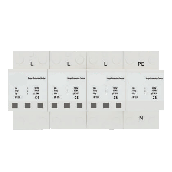
    Surge protection devices are installed at the point of entry of electrical and electronic equipment into the structure. These devices protect the equipment from voltage surges that can be caused by lightning strikes.

    The design of the lightning protection system must comply with the requirements of IEC 62561. The components must be selected based on their performance and safety requirements, and their placement must be determined based on the risk assessment.

    Step 3: Installation of the Lightning Protection System

    The installation of the lightning protection system must be carried out by qualified personnel who are familiar with the requirements of IEC 62561. The installation must comply with the relevant building codes and regulations.

    The installation process can be broken down into the following steps:

    • Installation of the air termination system
    • Installation of the down conductor system
    • Installation of the earth termination system
    • Installation of the surge protection devices

    Installation of the air termination system

    The air termination system is installed at the highest point of the structure. The air terminals must be installed in a manner that allows for the interception of the lightning strike. They must be spaced appropriately to ensure that the entire structure is covered.

    The air terminals must be securely fixed to the structure using appropriate fixings. They must be made of materials that are resistant to corrosion and mechanical damage. The air terminals must also be bonded to the down conductor system.

    Installation of the Down Conductor System

    The down conductor system is installed in a straight line from the air termination system to the earth termination system. The down conductors must be installed using appropriate fixings and must be secured to the structure at regular intervals.

    The down conductors must be made of materials that are resistant to corrosion and mechanical damage. They must also be bonded to the earth termination system and the surge protection devices. The down conductor system must also be installed in a manner that prevents water ingress and damage to the structure.

    Installation of the Earth Termination System

    The earth termination system is installed in the ground. The earth electrodes must be installed in a manner that ensures good electrical contact with the surrounding soil. The earth electrodes must be spaced appropriately to ensure that the entire lightning protection system is properly earthed.

    The earth electrodes must be made of materials that are resistant to corrosion and mechanical damage. They must also be bonded to the down conductor system and the surge protection devices.

    Installation of the Surge Protection Devices

    The surge protection devices are installed at the point of entry of electrical and electronic equipment into the structure. The devices must be installed in a manner that ensures good electrical contact and proper bonding to the down conductor system and earth termination system.

    The surge protection devices must be selected based on their performance and safety requirements. They must be installed in accordance with the manufacturer’s instructions and the requirements of IEC 62561.

    Step 4: Testing and Inspection

    Once the lightning protection system has been installed, it must be tested and inspected to ensure that it is functioning properly. The testing and inspection process should be carried out by qualified personnel who are familiar with the requirements of IEC 62561.

    The testing and inspection process should include the following:

    • Verification of the components and their installation
    • Measurement of the earth resistance of the earth termination system
    • Measurement of the continuity of the down conductor system
    • Verification of the bonding between components
    • Verification of the surge protection devices

    Any deficiencies or faults in the lightning protection system must be identified and rectified before the system is put into service.

    Step 5: Maintenance

    The lightning protection system must be regularly maintained to ensure that it continues to function properly. The maintenance should be carried out by qualified personnel who are familiar with the requirements of IEC 62561.

    The maintenance should include the following:

    • Inspection of the components for signs of damage or corrosion
    • Inspection of the fixings and connections for tightness and security
    • Measurement of the earth resistance of the earth termination system
    • Measurement of the continuity of the down conductor system
    • Verification of the bonding between components
    • Verification of the surge protection devices

    Any deficiencies or faults in the lightning protection system must be identified and rectified promptly to ensure that the system continues to provide adequate protection.

    The installation process of a lightning protection system must be carried out carefully and in accordance with the requirements of IEC 62561. The process involves a risk assessment, design of the lightning protection system, installation of the components, testing and inspection, and maintenance.

    The lightning protection system must be installed by qualified personnel who are familiar with the requirements of IEC 62561. The components must be selected based on their performance and safety requirements, and their placement must be determined based on the risk assessment.

    Regular maintenance of the lightning protection system is critical to ensure that it continues to function properly. The maintenance should be carried out by qualified personnel and should include inspection of the components, measurement of the earth resistance and continuity of the down conductor system, and verification of the surge protection devices.

    Adherence to the requirements of IEC 62561 is critical to ensure that the lightning protection system provides adequate protection to the structure and its contents. By following the installation process as per IEC 62561, the risk of damage or injury due to lightning strikes can be greatly reduced.

  • Best type of earthing

    Earthing is an essential aspect of electrical systems, as it protects people and equipment from the dangers of electrical faults. Electrical faults can occur due to various reasons, such as lightning strikes, equipment failure, and insulation breakdown. In such situations, earthing provides a low impedance path to ground, which prevents electrical currents from flowing through people and equipment. There are several types of earthing systems, and in this article, we will discuss chemical earthing, which is considered the best type of earthing. We will also discuss the components of chemical earthing, such as copper bonded rods, earth enhancement compounds, and FRP earth pit covers, which make it superior to conventional earthing.

    Conventional Earthing

    Conventional earthing involves burying a metal conductor, such as a copper rod or a galvanized iron pipe, in the ground. The conductor is connected to the electrical system, and its other end is buried deep in the ground. The depth of the conductor depends on several factors, such as the type of soil, the moisture content, and the electrical load. The objective of conventional earthing is to provide a low impedance path to ground, which limits the voltage rise in the event of an electrical fault.

    Conventional earthing has several limitations, which make it less effective compared to chemical earthing. Some of these limitations include:

    Corrosion – Metal conductors used in conventional earthing are prone to corrosion, which reduces their effectiveness over time. Corrosion can also lead to an increase in the resistance of the conductor, which results in higher voltage drops.

    Soil Conditions – The effectiveness of conventional earthing depends on soil conditions, such as moisture content and soil resistivity. In dry soils, the resistance of the conductor may increase, reducing its effectiveness.

    Maintenance – Conventional earthing requires regular maintenance, such as cleaning and inspection, to ensure its effectiveness. Neglecting maintenance can lead to corrosion and increased resistance.

    Chemical Earthing

    Chemical earthing, also known as maintenance-free earthing, is a modern type of earthing that overcomes the limitations of conventional earthing. Chemical earthing involves burying a copper bonded rod in the ground, which is filled with a conductive compound known as earth enhancement compound (EEC). The EEC is a mixture of conductive salts and minerals that provide a low impedance path to ground, even in dry soils. The EEC is also resistant to corrosion, which ensures the longevity of the earthing system.

    Components of Chemical Earthing

    Copper Bonded Rods

    Copper bonded rods are the main component of chemical earthing. These rods are made by bonding a layer of copper to a steel core using a high-pressure process. The copper layer provides excellent conductivity, while the steel core provides strength and durability. Copper bonded rods are available in different lengths and diameters, depending on the electrical load and soil conditions.

    Earth Enhancement Compound (EEC)

    The earth enhancement compound is a mixture of conductive salts and minerals that are used to fill the borehole around the copper bonded rod. The EEC is designed to improve the conductivity of the soil, even in dry conditions. The EEC is also resistant to corrosion, which ensures the longevity of the earthing system. The EEC is available in different grades, depending on the soil conditions and electrical load.

    FRP Earth Pit Cover

    FRP earth pit covers are used to cover the borehole and the EEC to protect them from environmental factors, such as rain, dust, and animals. FRP (Fiber Reinforced Plastic) is a lightweight and durable material that is resistant to corrosion and UV radiation. FRP earth pit covers are available in different sizes and shapes, depending on the size of the borehole and the electrical load.

    Advantages of Chemical Earthing

    Chemical earthing has several advantages over conventional earthing, some of which include:

    Low Impedance

    Chemical earthing provides a low impedance path to ground, which limits the voltage rise in the event of an electrical fault. This reduces the risk of electrical shocks and equipment damage.

    Improved Conductivity

    The earth enhancement compound used in chemical earthing improves the conductivity of the soil, even in dry conditions. This ensures the effectiveness of the earthing system, regardless of the soil conditions.

    Resistance to Corrosion

    Copper bonded rods used in chemical earthing are resistant to corrosion, which ensures the longevity of the earthing system. The EEC is also resistant to corrosion, which further improves the effectiveness of the earthing system.

    Maintenance-Free

    Chemical earthing is a maintenance-free system, which reduces the maintenance costs and ensures the reliability of the earthing system.

    Easy Installation

    Chemical earthing is easy to install and requires minimal excavation. The installation process involves drilling a borehole, inserting the copper bonded rod, and filling the borehole with the earth enhancement compound. The FRP earth pit cover is then installed to protect the borehole and the EEC.

    Applications of Chemical Earthing

    Chemical earthing is used in a wide range of applications, some of which include:

    Telecommunications – Chemical earthing is used in telecommunications systems to protect the equipment from lightning strikes and electrical faults. The low impedance path to ground provided by chemical earthing ensures the safety of the equipment and the personnel.

    Power Generation – Chemical earthing is used in power generation systems to protect the generators, transformers, and switchgear from electrical faults. The improved conductivity and resistance to corrosion provided by chemical earthing ensure the reliability of the electrical system.

    Data Centers – Chemical earthing is used in data centers to protect the servers and other equipment from electrical faults. The low impedance path to ground provided by chemical earthing ensures the safety of the equipment and the data stored in the servers.

    Industrial Applications – Chemical earthing is used in industrial applications, such as chemical plants, oil and gas facilities, and manufacturing plants. The improved conductivity and resistance to corrosion provided by chemical earthing ensure the safety of the personnel and the equipment.

    Chemical earthing is the best type of earthing system, as it overcomes the limitations of conventional earthing and provides a low impedance path to ground. The components of chemical earthing, such as copper bonded rods, earth enhancement compounds, and FRP earth pit covers, make it superior to conventional earthing in terms of conductivity, corrosion resistance, and maintenance-free operation. Chemical earthing is used in a wide range of applications, such as telecommunications, power generation, data centers, and industrial applications, to ensure the safety of the equipment and the personnel. If you are considering earthing for your electrical system, chemical earthing is the best choice for improved reliability and safety.

  • Exothermic welding process in earthing

    Exothermic welding process in earthing involves connecting a ground rod to an earthing conductor using an exothermic welding process. The ground rod is typically made of copper or steel and is inserted into the earth to create a low-impedance connection with the earth. The earthing conductor is typically made of copper or aluminum and is connected to the ground rod using an exothermic welding process.

    The exothermic welding process creates a permanent, high-quality connection between the ground rod and the earthing conductor. This connection is resistant to corrosion and is capable of carrying high current loads.

    The exothermic welding process in earthing involves the following steps:

    Preparation

    The first step in the exothermic welding process is to prepare the ground rod and earthing conductor. The ground rod should be cleaned and free of any corrosion or other contaminants. The earthing conductor should be cut to the required length and the insulation removed from the ends.

    Mould Preparation

    The next step is to prepare the mould for the welding process. The mould is a ceramic or graphite crucible that holds the welding material and provides the shape for the weld. The mould should be clean and free of any debris or contaminants.

    Welding Material Preparation

    The welding material is a mixture of metal powder and a chemical igniter. The metal powder is typically a mixture of copper oxide and aluminum powder. The chemical igniter is typically a mixture of iron oxide and aluminum powder. The welding material should be mixed thoroughly to ensure that the metal powder and chemical igniter are evenly distributed.

    Connection of Ground Rod and Earthing Conductor

    The ground rod and earthing conductor are connected to the mould using special clamps. The clamps should be tightened securely to ensure that the connection is stable during the welding process.

    Ignition of Welding Material

    The welding material is ignited using a spark igniter or a flint igniter. The chemical reaction between the metal powder and chemical igniter produces heat and molten metal. The heat and molten metal flow into the mould and create a permanent connection between the ground rod and earthing conductor.

    Cooling and Finishing

    After the welding process is complete, the mould is left to cool for several minutes. Once the mould is cool, the clamps are removed, and the excess material is removed using a cutting tool. The finished weld should be visually inspected to ensure that it is of high quality and free of any defects.

    Applications of Exothermic Welding in Earthing

    Exothermic welding is widely used in earthing applications for various purposes. Some of the common applications of exothermic welding in earthing are:

    Lightning Protection

    Exothermic welding is used in lightning protection systems to create a low-impedance connection between the lightning rod and the earthing conductor. This low-impedance connection ensures that the lightning energy is safely discharged into the earth.

    Telecommunications

    Exothermic welding is used in telecommunications systems to create a low-impedance connection between the equipment and the earth. This low-impedance connection ensures that the equipment is properly grounded and protected from electrical faults and lightning strikes.

    Power Distribution

    Exothermic welding is used in power distribution systems to create a low-impedance connection between the transformer and the earth. This low-impedance connection ensures that the transformer is properly grounded and protected from electrical faults and lightning strikes.

    Railway Electrification

    Exothermic welding is used in railway electrification systems to create a low-impedance connection between the railway track and the earth. This low-impedance connection ensures that the railway system is properly grounded and protected from electrical faults and lightning strikes.

    Industrial Applications

    Exothermic welding is widely used in industrial applications to create low-impedance connections for equipment grounding, lightning protection, and other earthing applications. It is ideal for use in harsh and corrosive environments where a strong and reliable connection is required.

    Benefits of Exothermic Welding in Earthing

    Exothermic welding provides several benefits in earthing applications, including:

    Low Impedance Connection

    Exothermic welding creates a low-impedance connection between the ground rod and the earthing conductor. This low-impedance connection ensures that electrical equipment is properly grounded and protected from electrical faults and lightning strikes.

    Resistance to Corrosion

    Exothermic welding creates a connection that is resistant to corrosion. This is important in earthing applications where the connection is exposed to moisture and other corrosive elements.

    Easy to Use

    Exothermic welding is easy to use and does not require specialized skills. This makes it an ideal method of earthing for both professionals and DIY enthusiasts.

    Long-Lasting Connection

    Exothermic welding creates a permanent connection between the ground rod and the earthing conductor. This connection is resistant to corrosion and can withstand the test of time.

    Strong Connection

    Exothermic welding provides a strong connection that can withstand the test of time and environmental conditions. It is ideal for use in harsh and corrosive environments.

    Suitable for Various Metals

    Exothermic welding can be used to join various metals, including copper, aluminum, and steel. This makes it a versatile method of earthing that can be used in a wide range of applications.

    Exothermic welding is a widely used method of creating low-impedance connections in earthing applications. It provides several benefits, including a low-impedance connection, long-lasting connection, resistance to corrosion, strong connection, versatility, ease of use, and safety. Exothermic welding is widely used in various applications, including lightning protection, telecommunications, power distribution, railway electrification, and industrial applications. The exothermic welding process in earthing involves preparing the ground rod and earthing conductor, preparing the mould, preparing the welding material, connecting the ground rod and earthing conductor to the mould, igniting the welding material, and cooling and finishing the weld. By using exothermic welding in earthing applications, you can ensure that your electrical equipment is properly grounded and protected from electrical faults and lightning strikes.

  • IEC 62561-7 standard

    The IEC 62561-7 standard is part of the IEC 62561 series of standards that provides requirements and guidance for lightning protection systems. Part 7 of the series, titled “Requirements for earthing enhancing compounds,” specifies the requirements for earthing enhancing compounds (EECs) used in lightning protection systems. This article will provide an overview of the IEC 62561-7 standard, including its scope, requirements, and application.

    Scope of the Standard

    The IEC 62561-7 standard applies to EECs used in lightning protection systems. EECs are substances that are applied to the soil or earth electrode to improve the conductivity of the soil and enhance the earthing of the lightning protection system. EECs are used to reduce the resistance of the soil and improve the performance of the earth electrode, which in turn improves the effectiveness of the lightning protection system.

    The scope of the standard includes the requirements for the material properties, application methods, and performance characteristics of EECs used in lightning protection systems. The standard also specifies the procedures for testing and verifying the performance of EECs.

    Earth Enhancement Compound
    Earth Enhancement Compound

    Requirements for Earthing Enhancing Compounds

    The IEC 62561-7 standard specifies the requirements for the material properties, application methods, and performance characteristics of EECs used in lightning protection systems. These requirements are intended to ensure that EECs are effective in improving the conductivity of the soil and enhancing the earthing of the lightning protection system.

    Material Properties:

    The standard specifies the material properties that EECs must meet in order to be considered suitable for use in lightning protection systems. EECs must be non-toxic, non-flammable, and environmentally friendly. The standard also specifies requirements for the pH value, electrical conductivity, and water content of EECs.

    Application Methods:

    The standard specifies the procedures for the application of EECs to the soil or earth electrode. The application method should be such that the EEC is uniformly distributed and adequately covers the area of the soil or earth electrode.

    Performance Characteristics:

    The standard specifies the performance characteristics that EECs must meet in order to be considered effective in improving the conductivity of the soil and enhancing the earthing of the lightning protection system. EECs must have a low resistance and be able to maintain their conductivity over time. The standard also specifies the procedures for testing and verifying the performance of EECs.

    Testing and Verification of Performance

    The IEC 62561-7 standard specifies the procedures for testing and verifying the performance of EECs used in lightning protection systems. These procedures are intended to ensure that EECs are effective in improving the conductivity of the soil and enhancing the earthing of the lightning protection system.

    The standard specifies the procedures for measuring the resistance of the soil and the earth electrode with and without the application of EECs. The resistance measurements should be taken before and after the application of EECs to determine the effectiveness of the EECs in reducing the resistance of the soil and improving the performance of the earth electrode.

    The standard also specifies the procedures for testing the conductivity of the soil and the earth electrode with and without the application of EECs. The conductivity measurements should be taken before and after the application of EECs to determine the effectiveness of the EECs in enhancing the earthing of the lightning protection system.

    Application of the Standard

    The IEC 62561-7 standard is intended to be used by designers, installers, and maintainers of lightning protection systems. The standard provides guidance on the selection, application, and performance verification of EECs used in lightning protection systems.

    Designers of lightning protection systems can use the standard to ensure that the EECs used in their systems meet the material properties, application methods, and performance characteristics specified in the standard. This can help to ensure the effectiveness of the lightning protection system in protecting the structure and its occupants from lightning strikes.

    Installers of lightning protection systems can use the standard to ensure that the EECs are applied correctly and according to the specified procedures. This can help to ensure that the EECs are evenly distributed and adequately cover the area of the soil or earth electrode, which is necessary for their effective performance.

    Maintainers of lightning protection systems can use the standard to verify the performance of the EECs over time. Regular testing and verification of the EECs can help to ensure that they are still effective in improving the conductivity of the soil and enhancing the earthing of the lightning protection system.

    Benefits of the IEC 62561-7 Standard

    The IEC 62561-7 standard provides several benefits to the lightning protection industry. These benefits include:

    1. Improved Effectiveness of Lightning Protection Systems: The use of EECs that meet the requirements specified in the standard can help to improve the effectiveness of lightning protection systems. This can help to reduce the risk of damage to structures and their occupants from lightning strikes.
    2. Standardization: The IEC 62561-7 standard provides a standardized approach to the selection, application, and performance verification of EECs used in lightning protection systems. This can help to ensure consistency and reliability in the use of EECs across different projects and locations.
    3. Quality Assurance: The standard provides a framework for the testing and verification of the performance of EECs. This can help to ensure that the EECs are effective in improving the conductivity of the soil and enhancing the earthing of the lightning protection system, and can help to provide quality assurance to stakeholders.
    4. Environmental Protection: The standard specifies requirements for the environmental friendliness of EECs, including their non-toxicity and non-flammability. This can help to ensure that the use of EECs does not have negative impacts on the environment.

    The IEC 62561-7 standard provides requirements and guidance for the use of earthing enhancing compounds (EECs) in lightning protection systems. The standard specifies the material properties, application methods, and performance characteristics that EECs must meet in order to be effective in improving the conductivity of the soil and enhancing the earthing of the lightning protection system. The standard also specifies the procedures for testing and verifying the performance of EECs.

    The IEC 62561-7 standard provides several benefits to the lightning protection industry, including improved effectiveness of lightning protection systems, standardization, quality assurance, and environmental protection. The standard is intended to be used by designers, installers, and maintainers of lightning protection systems to ensure that the EECs used in their systems meet the requirements specified in the standard and are effective in improving the conductivity of the soil and enhancing the earthing of the lightning protection system.

  • Earthing materials in Patna, Bihar

    Earthing refers to the process of connecting the electrical system of a building to the ground to protect it from surges and lightning strikes. The process is essential for the safe operation of electrical systems, as it provides a low resistance path for electricity to flow to the earth in case of any faults.

    Patna, the capital of Bihar, is a rapidly developing city that has witnessed a significant increase in the number of buildings and infrastructure projects over the last decade. These developments require proper earthing systems to ensure the safety of the buildings and the people inside them.

    There are two types of earthing systems: conventional earthing and chemical earthing. In this article, we will discuss both types of earthing systems and the earthing materials used in Patna, Bihar.

    Conventional Earthing System

    Conventional earthing systems have been in use for many years and involve the use of earthing pipes, earthing rods, charcoal, salt, and other materials. These materials are easily available and cost-effective, making them a popular choice for conventional earthing systems.

    Earthing Pipe

    Earthing pipes are a type of metal pipe that is installed vertically in the ground. The pipe is made of copper or GI (Galvanized Iron) and is buried in a pit that is filled with a mixture of charcoal and salt. The earthing pipe is connected to the electrical system of the building, and the earth wire is attached to the pipe.

    The earthing pipe is an effective way to provide a low resistance path for electrical currents to flow to the ground. The salt and charcoal mixture in the pit helps to maintain the moisture level in the soil, which is essential for effective earthing.

    Earthing Rod

    Earthing rods are another type of earthing material that is commonly used in conventional earthing systems. The rod is made of copper or GI and is installed vertically in the ground. The earthing rod is connected to the electrical system of the building, and the earth wire is attached to the rod.

    The earthing rod is effective in providing a low resistance path for electrical currents to flow to the ground. However, the rod requires a large amount of space in the ground, and the installation process can be challenging.

    Charcoal and Salt

    Charcoal and salt are commonly used in conventional earthing systems to maintain the moisture level in the soil around the earthing material. The moisture helps to provide a low resistance path for electrical currents to flow to the ground.

    The charcoal and salt mixture is filled in the earthing pit around the earthing pipe or rod. The mixture needs to be replenished regularly to maintain the moisture level in the soil.

    Chemical Earthing System

    Chemical earthing systems are a relatively new technology that has gained popularity in recent years. The system involves the use of chemical compounds that are specially designed to enhance the conductivity of the soil around the earthing material. This results in a lower resistance path for electrical currents to flow to the ground.

    Copper Bonded Rod

    Copper bonded rods are one of the most commonly used earthing materials in chemical earthing systems. The rod is made of steel and is coated with a layer of copper that is bonded to the steel. The rod is installed vertically in the ground and connected to the electrical system of the building.

    The copper bonded rod provides an excellent low resistance path for electrical currents to flow to the ground. The copper coating helps to enhance the conductivity of the soil around the rod, resulting in a more efficient earthing system.

    Earth Enhancement Compound

    Earth enhancement compound is a chemical compound that is specially designed to enhance the conductivity of the soil around the earthing material. The compound is made of a mixture of natural materials and is added to the earthing pit around the earthing material.

    The compound helps to reduce the resistance of the soil and provides a efficient low resistance path for electrical currents to flow to the ground. It also helps to maintain the moisture level in the soil, reducing the need for regular replenishment of the earthing pit.

    FRP Earth Pit Cover

    FRP (Fiber Reinforced Plastic) earth pit covers are used to cover the earthing pit in chemical earthing systems. The covers are made of a durable and corrosion-resistant material that can withstand harsh weather conditions and provide protection to the earthing pit.

    The FRP earth pit covers are also designed to provide easy access to the earthing pit for maintenance and inspection purposes. They are available in various sizes and shapes to fit different types of earthing pits.

    Advantages and Disadvantages of Conventional and Chemical Earthing Systems

    Both conventional and chemical earthing systems have their advantages and disadvantages. Conventional earthing systems are cost-effective and easy to install, but they require regular maintenance to ensure their effectiveness. Chemical earthing systems, on the other hand, are more efficient and require less maintenance, but they can be more expensive than conventional systems.

    Conventional earthing systems are more prone to corrosion and can deteriorate over time, resulting in a higher resistance path for electrical currents to flow to the ground. Chemical earthing systems, on the other hand, are designed to last for many years and provide a consistent low resistance path for electrical currents.

    Earthing systems are an essential aspect of building safety and should be installed and maintained properly. Patna, Bihar, has seen significant development over the last decade, resulting in the need for proper earthing systems in buildings and infrastructure projects.

    Conventional earthing systems, such as earthing pipes, earthing rods, charcoal, and salt, are still widely used in Patna. However, chemical earthing systems, such as copper bonded rods, earth enhancement compounds, and FRP earth pit covers, are gaining popularity due to their efficiency and durability.

    Both conventional and chemical earthing systems have their advantages and disadvantages, and the choice of earthing system should depend on the specific requirements and budget of the project.

    Proper installation and maintenance of the earthing system are essential to ensure its effectiveness and safety. It is essential to consult with a qualified electrician or engineer to determine the appropriate earthing system and materials for the building or infrastructure project.

  • What is TT, TN and IT Earthing Systems

    Earthing is an essential aspect of any electrical installation. It is a system designed to protect people, equipment, and structures from electric shock and other hazards by providing a low-resistance path for electrical currents to flow to the earth. There are three commonly used earthing systems known as the TT, TN, and IT systems. In this article, we will discuss these earthing systems in detail.

    TT System

    In the TT system, the earthing electrode is connected to a local earth source, such as a rod or plate, and each piece of equipment is also connected to the same local earth. This system provides a low-resistance path for fault currents to flow to the earth, and is commonly used in areas where the soil resistivity is high.

    The TT system is considered to be the safest earthing system, as it provides a high level of protection against electric shock. It is also relatively easy to install and maintain, as each piece of equipment is connected to the same local earth source. However, the TT system can be more expensive than other earthing systems, as it requires the installation of additional earth electrodes.

    TN System

    In the TN system, the earthing electrode is directly connected to the power supply neutral. The TN system can be further subdivided into three types: TN-S, TN-C, and TN-C-S.

    TN-S System

    In the TN-S system, the power supply neutral is directly connected to the earthing electrode, and each piece of equipment is connected to the same earthing electrode. This system provides a low-resistance path for fault currents to flow to the earth.

    The TN-S system is commonly used in low-voltage electrical installations, as it is simple to install and provides a high level of protection against electric shock. However, this system can be less effective in areas where the soil resistivity is high, as the earth resistance can be too high to provide adequate protection.

    TN-C System

    In the TN-C system, the power supply neutral and the earthing conductor are combined into a single conductor, known as the combined neutral and earth (CNE) conductor. Each piece of equipment is then connected to the CNE conductor, providing a low-resistance path for fault currents to flow to the earth.

    The TN-C system is also known as the combined system, as the neutral and earth are combined into a single conductor. This system is commonly used in low-voltage electrical installations, as it is simple to install and provides a high level of protection against electric shock. However, this system can be less effective in areas where the soil resistivity is high, as the earth resistance can be too high to provide adequate protection.

    TN-C-S System

    The TN-C-S system is a combination of the TN-S and TN-C systems. In this system, the power supply neutral is connected to the earthing electrode, and the CNE conductor is used to connect each piece of equipment to the earthing system.

    The TN-C-S system is commonly used in low-voltage electrical installations, as it provides a high level of protection against electric shock and is relatively easy to install and maintain. However, this system can be less effective in areas where the soil resistivity is high, as the earth resistance can be too high to provide adequate protection.

    IT System

    In the IT system, the power supply neutral is not directly connected to the earth. Instead, each piece of equipment is isolated from the earth and connected to an isolated earthing transformer, which in turn is connected to the earthing electrode. This system provides a high level of safety against electric shock, as the fault current is limited by the impedance of the transformer.

    The IT system is commonly used in high-voltage electrical installations, as it provides a high level of protection against electric shock and is relatively easy to install and maintain. However, this system can be more complex and expensive than other earthing systems, as it requires the installation of an isolated transformer and additional earthing electrodes.

    Advantages and Disadvantages of Each System

    Each earthing system has its advantages and disadvantages, and the choice of system depends on a variety of factors, such as the type of installation, soil resistivity, and level of protection required.

    The TT system provides the highest level of safety against electric shock, but it can be more expensive to install and maintain, especially in areas with high soil resistivity.

    The TN-S system is simple to install and provides a high level of protection against electric shock. However, it can be less effective in areas with high soil resistivity.

    The TN-C system is also simple to install and provides a high level of protection against electric shock. However, it can be less effective in areas with high soil resistivity, and there is a risk of electric shock if the CNE conductor is damaged.

    The TN-C-S system combines the advantages of the TN-S and TN-C systems and is commonly used in low-voltage electrical installations. However, it can be less effective in areas with high soil resistivity.

    The IT system provides a high level of safety against electric shock, but it can be more complex and expensive to install and maintain.

    Earthing is an essential aspect of any electrical installation, as it provides a low-resistance path for fault currents to flow to the earth, protecting people, equipment, and structures from electric shock and other hazards. There are three commonly used earthing systems: the TT, TN, and IT systems.

    The choice of earthing system depends on a variety of factors, such as the type of installation, soil resistivity, and level of protection required. Each system has its advantages and disadvantages, and it is important to choose the system that provides the highest level of protection while also being cost-effective and easy to install and maintain.

  • What is Earthing Formula?

    Earthing Formula:

    The formula for calculating the resistance of an earthing system is:

    R = ρ x (2πL / A)

    Where:
    R is the resistance of the earthing system
    ρ is the resistivity of the soil
    L is the length of the earthing electrode
    A is the cross-sectional area of the earthing electrode

    The earthing formula is used to determine the effectiveness of an earthing system in dissipating electrical energy to the ground. The formula takes into account the soil resistivity, the length and cross-sectional area of the earthing electrode. The soil resistivity is an important parameter that affects the effectiveness of the earthing system. The resistivity of the soil varies depending on the type of soil, moisture content, temperature, and other factors. The length and cross-sectional area of the earthing electrode are also important factors that affect the resistance of the earthing system. The longer the electrode and the larger the cross-sectional area, the lower the resistance of the earthing system.

    Soil Resistivity:

    Soil resistivity is a measure of the resistance of soil to the flow of electrical current. The resistivity of the soil depends on the type of soil, moisture content, temperature, and other factors. The resistivity of soil is expressed in ohm-meters (Ω-m). The resistivity of soil can be determined by performing soil resistivity tests using specialized equipment. The soil resistivity is an important parameter that affects the effectiveness of the earthing system. The lower the soil resistivity, the better the earthing system is at providing protection against electrical hazards.

    Length and Cross-Sectional Area of the Earthing Electrode:

    The length and cross-sectional area of the earthing electrode are also important factors that affect the resistance of the earthing system. The length of the electrode determines the depth at which the electrode is buried in the ground. The deeper the electrode, the lower the resistance of the earthing system. The cross-sectional area of the electrode determines the amount of current that can flow through the electrode. The larger the cross-sectional area, the lower the resistance of the earthing system.

    Designing an Earthing System:

    Designing an earthing system requires careful consideration of the soil conditions, electrical loads, and the requirements of national and international electrical standards. The earthing system should be designed to provide a low-resistance path for electrical current to flow to the earth. The resistance of the earthing system should be within the acceptable range for the specific application.

    The first step in designing an earthing system is to determine the soil resistivity. This can be done by performing soil resistivity tests using specialized equipment. The results of the soil resistivity tests are used to determine the length and cross-sectional area of the earthing electrode.

    The next step is to determine the electrical loads that will be connected to the earthing system. This includes the electrical equipment, lighting, and other loads that will be connected to the electrical system. The electrical loads are used to determine the size of the earthing conductor and the number of electrodes that are required.

    The earthing conductor is the cable that connects the electrical equipment to the earthing system. The size of the earthing conductor is determined by the maximum fault current that can flow through the equipment. The earthing conductor should be sized to handle the maximum fault current without overheating or melting.

    The number of electrodes that are required is determined by the size of the electrical load and the soil resistivity. The electrodes should be spaced apart at a distance that ensures that the electrical current is distributed evenly throughout the soil.

    The earthing system should be designed to comply with national and international electrical standards. These standards specify the minimum requirements for earthing systems in different applications. The standards also provide guidelines for testing and verifying the effectiveness of the earthing system.

    Testing and Verification of Earthing Systems:

    Testing and verification of earthing systems is an important step in ensuring that the earthing system is effective in providing protection against electrical hazards. The effectiveness of the earthing system is determined by the resistance of the earthing system. The resistance of the earthing system should be within the acceptable range for the specific application.

    The testing and verification of the earthing system should be done by a qualified electrical engineer or technician. The testing should be done using specialized equipment that is designed for measuring the resistance of the earthing system.

    The testing should be done after the earthing system has been installed and before the electrical equipment is connected to the earthing system. The testing should also be done periodically to ensure that the earthing system remains effective over time.

    Earthing or grounding is an essential safety feature in electrical installations. The earthing system provides a low-resistance path for electrical current to flow to the earth, preventing electrical shocks, fires, and damage to equipment. The effectiveness of the earthing system is determined by the resistance of the earthing system. The earthing formula is used to calculate the resistance of the earthing system, taking into account the soil resistivity, the length and cross-sectional area of the earthing electrode.

    Designing an earthing system requires careful consideration of the soil conditions, electrical loads, and the requirements of national and international electrical standards. The earthing system should be designed to comply with these standards and to provide a low-resistance path for electrical current to flow to the earth.

    Testing and verification of earthing systems is an important step in ensuring that the earthing system is effective in providing protection against electrical hazards. The testing should be done periodically to ensure that the earthing system remains effective over time.

    In summary, the earthing formula is a critical tool for designing and verifying the effectiveness of earthing systems in electrical installations. By understanding the factors that affect the resistance of the earthing system, electrical engineers and technicians can design and install earthing systems that provide reliable protection against electrical hazards.

  • Which type of earthing is best?

    Earthing, also known as grounding, is an essential aspect of electrical systems. It involves connecting electrical equipment or installations to the earth or ground to protect people, animals, and equipment from electric shock and damage. Earthing also helps in reducing electrical noise, improving signal quality, and preventing electromagnetic interference. There are several types of earthing systems available, and selecting the best type of earthing for a particular installation depends on several factors. This article discusses the different types of earthing systems and their respective advantages and disadvantages to help determine which type of earthing is best.

    Plate Earthing

    Plate earthing is a type of earthing system where a copper or galvanized iron plate of size 60 cm x 60 cm x 3.18 mm is buried vertically in the ground. A connection is made between the plate and the electrical system to be earthed using a copper wire. Plate earthing is suitable for areas with dry soil conditions and low soil resistivity. It is easy to install, cost-effective, and requires minimal maintenance. However, plate earthing can be ineffective in areas with high soil resistivity and where the soil is prone to corrosion.

    Pipe Earthing

    Pipe earthing is a type of earthing system where a hollow galvanized steel or PVC pipe is buried vertically in the ground. The pipe is filled with alternate layers of charcoal and salt to improve the conductivity of the soil around the pipe. A copper wire is connected to the top of the pipe, and the other end is connected to the electrical system to be earthed. Pipe earthing is suitable for areas with high soil resistivity and moist soil conditions. It is also suitable for installations that require high fault current carrying capacity. However, pipe earthing requires periodic maintenance to refill the charcoal and salt layers, and the installation cost is relatively high.

    Rod Earthing

    Rod earthing is a type of earthing system where a copper or galvanized steel rod of length 2.5 m to 3 m is buried vertically in the ground. A connection is made between the rod and the electrical system to be earthed using a copper wire. Rod earthing is suitable for areas with dry soil conditions and low soil resistivity. It is easy to install, cost-effective, and requires minimal maintenance. However, rod earthing can be ineffective in areas with high soil resistivity and where the soil is prone to corrosion.

    Strip Earthing

    Strip earthing is a type of earthing system where a copper or galvanized iron strip of size 25 mm x 3 mm is buried horizontally in a trench of depth 0.75 m to 1 m. A connection is made between the strip and the electrical system to be earthed using a copper wire. Strip earthing is suitable for areas with high soil resistivity and moist soil conditions. It is also suitable for installations that require high fault current carrying capacity. However, strip earthing requires a large trench for installation, and the installation cost is relatively high.

    Chemical Earthing

    Chemical earthing is a type of earthing system that uses a backfill compound to improve the conductivity of the soil around the electrode. The electrode can be a copper pipe, rod, or plate. The backfill compound is a mixture of bentonite, salt, and graphite powder that is poured around the electrode. The compound absorbs moisture from the soil, and the salt helps in reducing soil resistivity. Chemical earthing is suitable for areas with high soil resistivity and where the soil is prone to corrosion. It is also suitable for installations that require high fault current carrying capacity. However, the installation cost is relatively high.

    Earth Mat Earthing

    Earth Mat earthing is a type of earthing system where a conductive mat made of copper or aluminum is laid on the surface of the earth. The mat is connected to the electrical system to be earthed using a copper wire. Earth mat earthing is suitable for installations with limited space and where there is no possibility of digging trenches or installing electrodes. It is also suitable for installations that require high fault current carrying capacity. However, earth mat earthing can be ineffective in areas with high soil resistivity, and it requires periodic maintenance to ensure the mat remains conductive.

    Combined Earthing

    Combined earthing is a type of earthing system that uses a combination of different types of earthing systems to provide a reliable and efficient earth. For example, a combination of rod earthing and strip earthing can be used in areas with varying soil resistivity. The rods are used in areas with low soil resistivity, while the strips are used in areas with high soil resistivity. Combined earthing is suitable for installations that require high fault current carrying capacity and where there is a need for a reliable and efficient earth. However, combined earthing requires careful design and planning to ensure the different types of earthing systems work together effectively.

    So, which type of earthing is best? The answer depends on several factors such as soil resistivity, moisture content, installation space, and fault current carrying capacity requirements. For example, in areas with dry soil conditions and low soil resistivity, plate earthing or rod earthing may be the best option. In areas with high soil resistivity and moist soil conditions, pipe earthing or strip earthing may be the best option. In installations with limited space, earth mat earthing may be the best option. In installations that require high fault current carrying capacity, chemical earthing or combined earthing may be the best option.

    It is essential to note that selecting the best type of earthing is just the first step. Proper installation and maintenance of the earthing system are crucial for it to work effectively. The earthing system must be installed according to the relevant codes and standards and regularly inspected and tested to ensure its integrity. Faults in the earthing system must be promptly identified and rectified to prevent electric shock or damage to equipment.

    In conclusion, selecting the best type of earthing system requires careful consideration of several factors such as soil resistivity, moisture content, installation space, and fault current carrying capacity requirements. Each type of earthing system has its advantages and disadvantages, and the best option depends on the specific installation requirements. Proper installation and maintenance of the earthing system are crucial for it to work effectively, and regular testing and inspection must be carried out to ensure its integrity.

  • Earthing materials and their functions

    Earthing, also known as grounding, is a critical safety practice in electrical engineering. It involves the connection of an electrical device or system to the earth, creating a path for electrical current to flow into the ground, thus preventing electrical shock and fire hazards. Earthing materials play a crucial role in ensuring that the electrical systems and devices are properly grounded, and they come in different types and functions. In this article, we will discuss the various types of earthing materials and their functions.

    Copper Earth Rods

    Copper earth rods are the most commonly used earthing material in electrical installations. They are made of high-quality copper material, which is an excellent conductor of electricity and is resistant to corrosion. The copper earth rods are installed vertically into the ground and are connected to the electrical system through a copper conductor. The copper rod acts as a lightning arrester, diverting electrical currents away from the electrical equipment or building and safely dispersing them into the ground.

    Copper Earthing Strips

    Copper earthing strips are another essential earthing material used in electrical installations. They are made of copper and come in various sizes, depending on the size of the electrical installation. Copper earthing strips are used to provide a low impedance path to ground for the electrical system. They are installed horizontally on the ground, typically beneath the foundation of the building, and are connected to the copper earth rod or copper conductor. Copper earthing strips are ideal for installations in areas where the ground is dry or rocky since they provide a larger contact area for better conductivity.

    Copper Earth Plates

    Copper earth plates are also commonly used earthing materials in electrical installations. They are made of copper and have a larger surface area than copper earth rods. The larger surface area of copper earth plates makes them ideal for installations in areas with high soil resistivity. They are installed horizontally into the ground and connected to the electrical system through a copper conductor. Copper earth plates act as a grounding electrode, providing a low impedance path to ground for the electrical system.

    Grounding Clamps

    Grounding clamps are essential earthing materials used in electrical installations to connect the copper conductor to the copper earth rod or plate. They are made of high-quality copper material and are designed to ensure a tight and secure connection between the copper conductor and the earth rod or plate. Grounding clamps are available in different sizes and shapes, depending on the size of the copper conductor and the earth rod or plate. They are easy to install and are suitable for use in different types of electrical installations.

    Earthing Mats

    Earthing mats are another essential earthing material used in electrical installations. They are made of conductive material and are installed on the floor of the building. Earthing mats are used to provide a low impedance path to ground for the electrical system. They are ideal for use in areas where the ground is not easily accessible, such as high-rise buildings. Earthing mats are connected to the electrical system through a copper conductor and are designed to ensure that the electrical equipment is properly grounded.

    Lightning Arrestors

    Lightning arrestors are essential earthing materials used in electrical installations to protect the electrical system from lightning strikes. They are installed on the top of the building and are connected to the electrical system through a copper conductor. Lightning arrestors are designed to divert lightning strikes away from the building and safely disperse them into the ground. They are made of high-quality materials that are resistant to corrosion and can withstand high temperatures and pressure.

    Earth Leakage Circuit Breakers (ELCB)

    Earth Leakage Circuit Breakers (ELCB) are essential earthing materials used in electrical installations to protect against electric shock. They are designed to detect any leakage current and cut off the electrical supply to the equipment or building. ELCB is installed in the electrical distribution panel and is connected to the earth rod or plate through a copper conductor. In the event of a leakage current, the ELCB immediately trips, cutting off the electrical supply and preventing any potential electrical shock. ELCBs are available in different types and ratings, depending on the type of electrical installation and the level of protection required.

    Earthing Chemicals

    Earthing chemicals are used to enhance the conductivity of the soil around the earth rod or plate. They are designed to improve the soil resistivity and ensure that the electrical system is properly grounded. Earthing chemicals are available in different types, depending on the type of soil and the level of conductivity required. They are typically mixed with water and poured around the earth rod or plate to enhance the soil conductivity.

    Earthing Conductors

    Earthing conductors are essential earthing materials used to connect the different components of the earthing system. They are made of copper or aluminum and come in different sizes and shapes, depending on the size of the electrical installation. Earthing conductors are used to provide a low impedance path to ground and ensure that the electrical system is properly grounded. They are typically connected to the copper earth rod or plate and are used to connect the various components of the earthing system.

    Earthing Clamps

    Earthing clamps are used to connect the earthing conductors to the different components of the earthing system. They are made of high-quality materials, such as copper or brass, and are designed to ensure a tight and secure connection between the earthing conductor and the component. Earthing clamps are available in different sizes and shapes, depending on the size of the earthing conductor and the component.

    In conclusion, earthing materials are essential components of any electrical installation. They play a crucial role in ensuring that the electrical system is properly grounded and that the equipment and building are protected against electrical shock and fire hazards. The different types of earthing materials, such as copper earth rods, copper earthing strips, copper earth plates, grounding clamps, earthing mats, lightning arrestors, ELCBs, earthing chemicals, earthing conductors, and earthing clamps, serve different functions but are all crucial in creating a safe and efficient electrical installation. It is important to choose the right type of earthing materials for your electrical installation to ensure that it is properly grounded and protected against electrical hazards.

  • Earthing in Kolkata

    Earthing System in Kolkata

    Earthing is an essential component of any electrical system as it ensures safety and proper functioning of the electrical installations. Kolkata, the capital city of the Indian state of West Bengal, is no exception when it comes to the importance of earthing.

    Kolkata, also known as the cultural capital of India, has a mix of old and new buildings, residential areas, commercial establishments, and industrial zones. These areas require different types of earthing systems depending on their usage, electrical load, and soil conditions.

    In Kolkata, the most common type of earthing system used is the plate earthing system. This system consists of a copper or galvanized iron plate buried in the ground with an earth wire connected to it. The plate is buried at a depth of around 2.5 to 3 meters to ensure proper contact with the soil. This system is most suitable for residential and small commercial establishments.

    For larger commercial establishments and industrial zones, the rod earthing system is used. This system consists of a copper or galvanized iron rod buried in the ground with an earth wire connected to it. The rod is driven into the ground to a depth of around 3 meters. The number of rods required for an establishment depends on the electrical load and soil conditions.

    Kolkata has a high water table and a humid climate, which can lead to corrosion of the earthing system. Therefore, it is important to use anti-corrosive materials like copper or galvanized iron for the earthing system.

    In addition to the plate and rod earthing systems, Kolkata also uses the pipe earthing system for large industrial establishments. This system consists of a pipe made of galvanized iron buried in the ground with an earth wire connected to it. The pipe is filled with a mixture of charcoal and salt, which improves the conductivity of the soil.

    Apart from these, Kolkata also uses the chemical earthing system, which is a relatively new technology that involves the use of conductive compounds to improve the conductivity of the soil. This system is maintenance-free and has a longer lifespan compared to traditional earthing systems.

    Conventional Earthing System in Kolkata

    Conventional earthing is the traditional method of grounding electrical systems, which has been used for many years in Kolkata. In this method, a copper or galvanized iron rod is installed in the ground to create a low-resistance path for current to flow to the earth. The depth of the rod installation is determined by the soil resistivity in the area.

    In Kolkata, the conventional earthing system typically involves a single electrode, which is connected to the electrical system through a copper conductor. The electrode is buried at a depth of around 2 to 3 meters in the soil. However, the quality of the earthing system depends on various factors such as the type of soil, moisture content, and the size of the electrode.

    One of the main disadvantages of the conventional earthing system is that it is not always reliable. The resistance of the earthing system can vary with changes in soil moisture, which can lead to an increase in the resistance of the system. This, in turn, can result in an increase in the potential difference between the system and the earth, which can be dangerous for individuals and property.

    Moreover, conventional earthing systems are not suitable for areas with high soil resistivity, such as rocky terrain, which is common in many parts of Kolkata. In these areas, it can be difficult to achieve a low-resistance path to the earth, and the conventional earthing system may not be able to provide adequate protection against electrical surges.

    In addition, conventional earthing systems require regular maintenance, including periodic measurement of earthing resistance, cleaning and inspection of the electrode, and replacement of corroded components. Failure to maintain the system can lead to a significant increase in the resistance of the earthing system and decrease its effectiveness.

    Therefore, in recent years, there has been a shift towards using chemical earthing systems in Kolkata.

    Chemical earthing system in Kolkata

    The chemical earthing system is an advanced earthing technology that utilizes conductive electrodes and earth enhancement compounds to provide low earth resistance and better grounding. The chemical earthing system involves the following steps:

    • A hole is dug in the ground to a depth of about 2-3 meters.
    • A conductive electrode, usually made of copper-bonded steel, is inserted into the hole.
    • The electrode is surrounded by a conductive and hygroscopic material called the earth enhancement compound, which enhances the conductivity of the soil and reduces earth resistance.
    • The electrode is connected to the equipment being earthed through a conductor or cable.
    • The earth resistance of the system is measured using a digital earth tester, and if the value is within the acceptable limits, the earthing is considered adequate.

    Chemical earthing systems are a modern solution to the problem of conventional earthing systems. They are designed to provide a low-resistance path to the earth, which is not affected by changes in soil moisture or resistivity. These systems use a conductive material, such as copper-bonded steel or graphite, to create an electrode that is buried in the ground.

    In Kolkata, chemical earthing systems have become increasingly popular due to their many advantages over conventional earthing systems. For instance, chemical earthing systems can provide a low-resistance path to the earth even in areas with high soil resistivity, making them suitable for use in rocky terrain. This can be particularly important in areas with a high incidence of lightning strikes, as it can help prevent electrical accidents and damage to property.

    Moreover, chemical earthing systems require minimal maintenance, making them more cost-effective in the long run. They do not require periodic measurement of earthing resistance, cleaning, or inspection, as they are designed to be maintenance-free. This can be particularly beneficial in Kolkata, where frequent power outages and voltage fluctuations can make it difficult to maintain a conventional earthing system.

    Additionally, chemical earthing systems are safer and more reliable than conventional earthing systems. They are designed to provide a low-resistance path to the earth, which reduces the risk of electrical accidents and ensures the safety of individuals and property. Moreover, chemical earthing systems are not affected by changes in soil moisture or resistivity, which can make them more reliable than Conventional Earthing.

    In conclusion, earthing is an essential safety measure for any electrical system, and Kolkata is no exception. While there are many conventional earthing systems used in the city, there are also new and innovative methods that are gaining popularity due to their effectiveness and reliability. The use of maintenance-free chemical earthing has many benefits over traditional earthing systems, including a longer lifespan, improved conductivity, and lower maintenance costs. It is important to note that the installation of earthing systems should always be carried out by qualified professionals to ensure safety and compliance with local regulations.

    Given the importance of earthing for electrical safety, it is essential that businesses and industries in Kolkata take the necessary steps to ensure that their earthing systems are up to code and functioning properly. This includes regular testing and maintenance to ensure that the earth resistance is within acceptable limits and that any potential faults are identified and addressed promptly. By investing in proper earthing systems, businesses and industries can help to prevent accidents and ensure the safety of their employees and equipment.

    Overall, earthing is an integral part of electrical safety in Kolkata, and it is essential that it is given the attention it deserves. With the right systems in place and proper installation and maintenance, businesses and industries in the city can enjoy safe and reliable electrical systems for years to come.