Blog

  • Different types of lightning protection systems

    Lightning is a powerful and potentially dangerous natural phenomenon that can strike without warning. It can cause significant damage to buildings, electrical systems, and people. To protect against lightning strikes, lightning protection systems (LPS) are installed in buildings and other structures. There are different types of lightning protection systems available, including direct and indirect lightning protection systems. In this article, we will discuss the different types of lightning protection systems in detail.

    Direct Lightning Protection Systems

    Direct lightning protection systems are designed to intercept and conduct lightning strikes to the ground, preventing damage to the structure and its occupants. These systems include lightning rods and early streamer emission (ESE) systems.

    Copper Lightning Arrester

    Franklin Rod LPS

    The Franklin rod LPS, also known as a lightning rod or air terminal, is the oldest and most common type of lightning protection system. It consists of a metal rod or a conductor installed at the highest point of a structure, typically on the roof. The rod or conductor is connected to a grounding system that provides a low-resistance path for the lightning to travel to the ground.

    When lightning strikes the structure, the Franklin rod LPS intercepts the strike and conducts it to the ground, dissipating the electrical energy harmlessly. The Franklin rod LPS works by creating a path of least resistance for the lightning to follow, reducing the risk of damage to the structure and its occupants.

    Franklin rod LPS is suitable for most buildings and structures, including residential and commercial buildings, factories, and high-rise buildings. They are relatively inexpensive and straightforward to install.

    ESE LPS

    Early Streamer Emission (ESE) LPS is a newer type of lightning protection system that is designed to attract and capture lightning strikes before they can damage a structure. ESE LPS use a special ionization system that emits a streamer of ions into the air before a lightning strike occurs. This ionization system creates an upward streamer, which can attract the lightning strike towards the system.

    ESE LPS is installed on the roof of the building and connected to the grounding system. They have a larger coverage area than Franklin rod LPS and are more sensitive to incoming lightning strikes. This makes them more effective at protecting large structures such as airports, wind turbines, and communication towers.

    ESE LPS is more expensive than Franklin rod LPS, but they are more effective and provide a higher level of protection. They are also easier to install and require less maintenance.

    Indirect Lightning Protection Systems

    Indirect lightning protection systems are designed to protect electrical systems and equipment from the effects of lightning strikes, such as power surges and voltage spikes. These systems include surge protection devices and grounding systems.

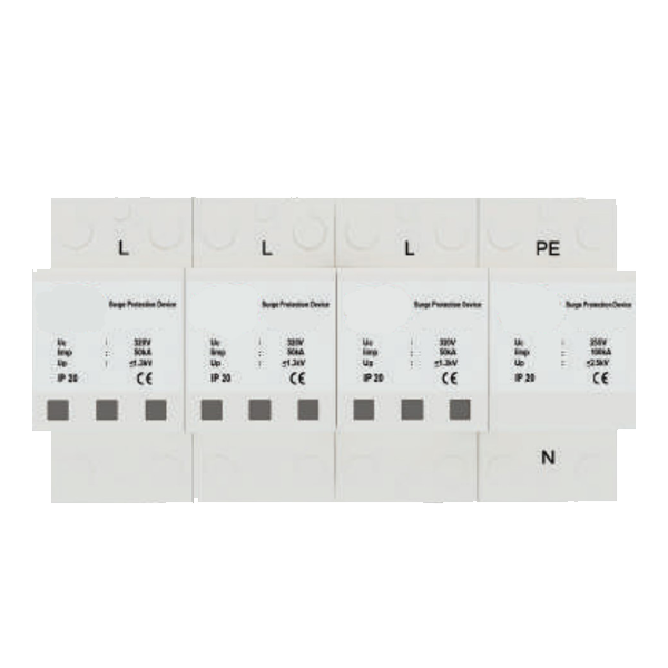
    Surge Protection Devices

    Surge protection devices (SPD) are electronic devices designed to protect electrical systems and equipment from power surges and voltage spikes caused by lightning strikes. They work by limiting the amount of electrical energy that can flow through the system, preventing damage to the equipment.

    SPDs are installed in the electrical system, typically at the point where the power enters the building. They are also installed on individual pieces of equipment to protect them from power surges. SPDs are available in different types, including plug-in, panel-mounted, and whole-house units.

    SPDs are effective at protecting electrical systems and equipment from lightning strikes, but they do not protect the structure from the physical effects of lightning strikes. They are also limited in their ability to protect against direct lightning strikes.
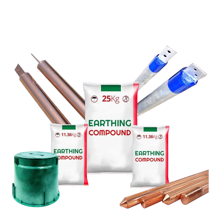
    Grounding Systems

    Grounding systems are an essential component of any lightning protection system. They provide a low-resistance path for the lightning to travel to the ground, dissipating the electrical energy harmlessly. Grounding systems consist of a network of conductive materials, including wires, rods, and plates, installed in the ground around the structure.

    Grounding systems work by creating a path of least resistance for the lightning to follow, reducing the risk of damage to the electrical system and equipment. They also provide a stable reference point for the electrical system, reducing the risk of electrical shocks and fires.

    Grounding systems are required by electrical codes and regulations and must be installed by qualified professionals. They must also be inspected and maintained regularly to ensure they are working correctly.

    Lightning is a powerful and potentially dangerous natural phenomenon that can cause significant damage to buildings, electrical systems, and people. To protect against lightning strikes, lightning protection systems (LPS) are installed in buildings and other structures.

    There are different types of lightning protection systems available, including direct and indirect lightning protection systems. Direct lightning protection systems are designed to intercept and conduct lightning strikes to the ground, preventing damage to the structure and its occupants. These systems include lightning rods and early streamer emission (ESE) systems.

    Indirect lightning protection systems are designed to protect electrical systems and equipment from the effects of lightning strikes, such as power surges and voltage spikes. These systems include surge protection devices and grounding systems.

    When selecting a lightning protection system, it is essential to consider the type of structure, the type of electrical system, and the level of protection required. It is also essential to hire qualified professionals to install and maintain the system to ensure it is working correctly.

    In conclusion, lightning protection systems are an essential component of any building or structure. By installing the right system, property owners can protect their investment and ensure the safety of their occupants.

  • IEC 62561-7 standard

    The IEC 62561-7 standard is part of the IEC 62561 series of standards that provides requirements and guidance for lightning protection systems. Part 7 of the series, titled “Requirements for earthing enhancing compounds,” specifies the requirements for earthing enhancing compounds (EECs) used in lightning protection systems. This article will provide an overview of the IEC 62561-7 standard, including its scope, requirements, and application.

    Scope of the Standard

    The IEC 62561-7 standard applies to EECs used in lightning protection systems. EECs are substances that are applied to the soil or earth electrode to improve the conductivity of the soil and enhance the earthing of the lightning protection system. EECs are used to reduce the resistance of the soil and improve the performance of the earth electrode, which in turn improves the effectiveness of the lightning protection system.

    The scope of the standard includes the requirements for the material properties, application methods, and performance characteristics of EECs used in lightning protection systems. The standard also specifies the procedures for testing and verifying the performance of EECs.

    Earth Enhancement Compound
    Earth Enhancement Compound

    Requirements for Earthing Enhancing Compounds

    The IEC 62561-7 standard specifies the requirements for the material properties, application methods, and performance characteristics of EECs used in lightning protection systems. These requirements are intended to ensure that EECs are effective in improving the conductivity of the soil and enhancing the earthing of the lightning protection system.

    Material Properties:

    The standard specifies the material properties that EECs must meet in order to be considered suitable for use in lightning protection systems. EECs must be non-toxic, non-flammable, and environmentally friendly. The standard also specifies requirements for the pH value, electrical conductivity, and water content of EECs.

    Application Methods:

    The standard specifies the procedures for the application of EECs to the soil or earth electrode. The application method should be such that the EEC is uniformly distributed and adequately covers the area of the soil or earth electrode.

    Performance Characteristics:

    The standard specifies the performance characteristics that EECs must meet in order to be considered effective in improving the conductivity of the soil and enhancing the earthing of the lightning protection system. EECs must have a low resistance and be able to maintain their conductivity over time. The standard also specifies the procedures for testing and verifying the performance of EECs.

    Testing and Verification of Performance

    The IEC 62561-7 standard specifies the procedures for testing and verifying the performance of EECs used in lightning protection systems. These procedures are intended to ensure that EECs are effective in improving the conductivity of the soil and enhancing the earthing of the lightning protection system.

    The standard specifies the procedures for measuring the resistance of the soil and the earth electrode with and without the application of EECs. The resistance measurements should be taken before and after the application of EECs to determine the effectiveness of the EECs in reducing the resistance of the soil and improving the performance of the earth electrode.

    The standard also specifies the procedures for testing the conductivity of the soil and the earth electrode with and without the application of EECs. The conductivity measurements should be taken before and after the application of EECs to determine the effectiveness of the EECs in enhancing the earthing of the lightning protection system.

    Application of the Standard

    The IEC 62561-7 standard is intended to be used by designers, installers, and maintainers of lightning protection systems. The standard provides guidance on the selection, application, and performance verification of EECs used in lightning protection systems.

    Designers of lightning protection systems can use the standard to ensure that the EECs used in their systems meet the material properties, application methods, and performance characteristics specified in the standard. This can help to ensure the effectiveness of the lightning protection system in protecting the structure and its occupants from lightning strikes.

    Installers of lightning protection systems can use the standard to ensure that the EECs are applied correctly and according to the specified procedures. This can help to ensure that the EECs are evenly distributed and adequately cover the area of the soil or earth electrode, which is necessary for their effective performance.

    Maintainers of lightning protection systems can use the standard to verify the performance of the EECs over time. Regular testing and verification of the EECs can help to ensure that they are still effective in improving the conductivity of the soil and enhancing the earthing of the lightning protection system.

    Benefits of the IEC 62561-7 Standard

    The IEC 62561-7 standard provides several benefits to the lightning protection industry. These benefits include:

    1. Improved Effectiveness of Lightning Protection Systems: The use of EECs that meet the requirements specified in the standard can help to improve the effectiveness of lightning protection systems. This can help to reduce the risk of damage to structures and their occupants from lightning strikes.
    2. Standardization: The IEC 62561-7 standard provides a standardized approach to the selection, application, and performance verification of EECs used in lightning protection systems. This can help to ensure consistency and reliability in the use of EECs across different projects and locations.
    3. Quality Assurance: The standard provides a framework for the testing and verification of the performance of EECs. This can help to ensure that the EECs are effective in improving the conductivity of the soil and enhancing the earthing of the lightning protection system, and can help to provide quality assurance to stakeholders.
    4. Environmental Protection: The standard specifies requirements for the environmental friendliness of EECs, including their non-toxicity and non-flammability. This can help to ensure that the use of EECs does not have negative impacts on the environment.

    The IEC 62561-7 standard provides requirements and guidance for the use of earthing enhancing compounds (EECs) in lightning protection systems. The standard specifies the material properties, application methods, and performance characteristics that EECs must meet in order to be effective in improving the conductivity of the soil and enhancing the earthing of the lightning protection system. The standard also specifies the procedures for testing and verifying the performance of EECs.

    The IEC 62561-7 standard provides several benefits to the lightning protection industry, including improved effectiveness of lightning protection systems, standardization, quality assurance, and environmental protection. The standard is intended to be used by designers, installers, and maintainers of lightning protection systems to ensure that the EECs used in their systems meet the requirements specified in the standard and are effective in improving the conductivity of the soil and enhancing the earthing of the lightning protection system.

  • Installation process as per NFC 17102

    The installation process as per NFC 17 102 2011 is a comprehensive guide that outlines the steps and procedures involved in the installation of lightning protection systems. This standard is used in many countries around the world, including France, and is designed to ensure that lightning protection systems are installed correctly and effectively. In this article, we will explore the installation process as per NFC 17 102 2011, including the steps involved and the requirements for each step.

    Overview of NFC 17 102 2011

    Before diving into the installation process, it is important to understand what NFC 17 102 2011 is and why it is important. This standard, also known as the French National Standard for Lightning Protection, provides guidelines for the design, installation, and maintenance of lightning protection systems. The standard applies to all types of structures, including buildings, bridges, and towers.

    The NFC 17 102 2011 standard is based on the principle of the Faraday cage, which is a conductive enclosure that protects the interior from external electrical fields. The standard recommends the installation of a lightning protection system that is designed to intercept lightning strikes and conduct the electrical current safely to the ground.

    Steps in the Installation Process

    The installation process as per NFC 17 102 2011 involves several steps that are designed to ensure that the lightning protection system is installed correctly and effectively. These steps are as follows:

    Site Survey

    The first step in the installation process is to conduct a site survey. This involves an inspection of the structure to determine the best location for the lightning protection system. The survey should take into account the height of the structure, the location of any metal objects, and the soil conditions.

    Design

    Once the site survey is complete, the lightning protection system can be designed. The design should take into account the size and shape of the structure, the local lightning density, and the protection level required. The design should also comply with the requirements of NFC 17 102 2011 and any other relevant standards.

    Installation of Air Terminals

    The next step is to install the air terminals. These are the rods or other conductive elements that are installed on the roof of the structure. The air terminals are designed to intercept the lightning strike and conduct the electrical current safely to the ground. The installation of air terminals should be done in accordance with the design and the requirements of NFC 17 102 2011.

    Installation of Down Conductors

    The down conductors are the vertical conductive elements that connect the air terminals to the ground. The down conductors should be installed in a straight line, without any sharp bends or kinks. The installation of down conductors should also comply with the requirements of NFC 17 102 2011.

    Installation of Grounding System

    The grounding system is the final part of the lightning protection system. It is designed to provide a safe path for the electrical current to dissipate into the ground. The grounding system should be installed in accordance with the design and the requirements of NFC 17 102 2011. The grounding system should also be tested to ensure that it is working correctly.

    Requirements for Each Step

    In addition to the steps involved in the installation process, there are also specific requirements for each step. These requirements are designed to ensure that the lightning protection system is installed correctly and effectively. The requirements for each step are as follows:

    Site Survey Requirements:

    • The site survey should be carried out by a qualified and experienced professional.
    • The survey should take into account the height of the structure, the location of any metal objects, and the soil conditions.
    • The survey should be documented in a report that includes recommendations for the design of the lightning protection system.

    Design Requirements:

    • The lightning protection system design should be carried out by a qualified and experienced professional.
    • The design should take into account the size and shape of the structure, the local lightning density, and the protection level required.
    • The design should comply with the requirements of NFC 17 102 2011 and any other relevant standards.
    • The design should include the location of the air terminals, down conductors, and grounding system.

    Air Terminal Installation Requirements:

    • The air terminals should be installed in accordance with the design and the requirements of NFC 17 102 2011.
    • The air terminals should be spaced no more than 20 meters apart.
    • The air terminals should be installed on the highest points of the structure and should be at least 1 meter above the roof.

    Down Conductor Installation Requirements:

    • The down conductors should be installed in a straight line, without any sharp bends or kinks.
    • The down conductors should be installed at least 50 cm away from the building’s exterior walls.
    • The down conductors should be connected to the air terminals with suitable connectors.
    • The down conductors should be made of a conductive material that meets the requirements of NFC 17 102 2011.

    Grounding System Installation Requirements:

    • The grounding system should be installed in accordance with the design and the requirements of NFC 17 102 2011.
    • The grounding system should be tested to ensure that it has a low resistance to earth.
    • The grounding system should be installed in an area that is not subject to flooding or waterlogging.
    • The grounding system should be connected to the down conductors with suitable connectors.
      Advantages of NFC 17 102 2011

    The NFC 17 102 2011 standard has several advantages when it comes to the installation of lightning protection systems. These advantages include:

    Clear Guidelines: NFC 17 102 2011 provides clear guidelines for the design, installation, and maintenance of lightning protection systems. This makes it easier for professionals to install the system correctly and effectively.

    High Protection Level: NFC 17 102 2011 requires lightning protection systems to provide a high level of protection against lightning strikes. This helps to ensure that the structure and its occupants are safe in the event of a lightning strike.

    International Standard: NFC 17 102 2011 is an international standard that is used in many countries around the world. This means that lightning protection systems installed according to the standard are likely to meet the requirements of other countries as well.

    Reliable Performance: NFC 17 102 2011 requires lightning protection systems to be designed and installed in a way that ensures reliable performance. This helps to reduce the risk of system failure and ensures that the system is effective in protecting the structure.

  • Installation of ESE Lightning protection

    Lightning strikes can cause significant damage to buildings and structures, resulting in costly repairs and downtime. The installation of a lightning protection system is critical to protect against the unpredictable and potentially dangerous effects of lightning strikes. One type of lightning protection system is the Early Streamer Emission (ESE) lightning protection system. In this article, we will discuss the installation process of the ESE lightning protection system and the advantages it offers over other types of systems. We will also explore the benefits of using maintenance-free chemical earthing instead of traditional earthing methods.

    What is an ESE Lightning Protection System?

    An ESE lightning protection system is designed to protect buildings and structures from direct and indirect lightning strikes. It works by emitting a streamer, which is an ionized channel that is capable of attracting lightning strikes. The ESE lightning protection system has a unique design that enables it to emit the streamer earlier than other types of systems, giving it an advantage in attracting lightning strikes.

    Installation Process of ESE Lightning Protection System

    The installation process of an ESE lightning protection system is similar to that of a conventional system. However, there are some differences due to the unique design of the ESE system. The installation process typically involves the following steps:

    Step 1: Site Assessment

    The first step in the installation process is a site assessment. This involves assessing the building or structure to determine the level of protection required. The assessment takes into account the size and shape of the building, the location, and the surrounding environment. The assessment is critical to ensuring that the ESE lightning protection system is designed to provide the necessary level of protection.

    Step 2: Design

    Once the site assessment is complete, the design of the ESE lightning protection system can begin. The design takes into account the results of the site assessment and is tailored to the specific needs of the building or structure. The design includes the placement of air terminals, conductors, and grounding system.

    Step 3: Installation of Air Terminals

    The air terminals are the most visible part of the lightning protection system. They are installed on the roof of the building or structure and are designed to attract lightning strikes. The air terminals are typically made of SS Metal.

    Step 4: Installation of Conductors

    The conductors are the cables that connect the air terminals to the grounding system. They are designed to conduct the electrical charge from a lightning strike safely into the ground. The conductors are typically made of copper or aluminum and are installed along the roof and down the sides of the building.

    Step 5: Installation of Grounding System

    The grounding system is designed to provide a path for the electrical charge from a lightning strike to safely dissipate into the ground. The grounding system typically consists of grounding rods and conductors that are buried in the ground. The grounding rods are installed at a sufficient depth to ensure a good connection with the soil.

    Advantages of ESE Lightning Protection System

    There are several advantages to using an ESE lightning protection system over other types of systems. These include:

    Early Streamer Emission

    The unique design of the ESE system enables it to emit a streamer earlier than other types of systems. This gives it an advantage in attracting lightning strikes, providing an extra layer of protection.

    High Level of Protection

    The ESE lightning protection system is designed to provide a high level of protection to buildings and structures. It is capable of protecting against direct and indirect lightning strikes, reducing the risk of damage and downtime.

    Low Maintenance

    The ESE lightning protection system requires little maintenance once it is installed. The air terminals and conductors are designed to withstand the elements and do not require regular maintenance.

    Cost-effective

    The ESE lightning protection system is a Cost-effective Lightning Protection Solution with Maintenance-Free Chemical Earthing.

    In addition to the advantages of the ESE lightning protection system, there is another important aspect of lightning protection that should be considered: earthing. Earthing is the process of providing a path for the electrical charge from a lightning strike to safely dissipate into the ground. The traditional method of earthing involves using a grounding rod or plate that is buried in the ground. However, this method can be unreliable and requires regular maintenance to ensure a good connection with the soil.

    A more modern and effective approach to earthing is the use of maintenance-free chemical earthing. This involves using a conductive compound that is mixed with the soil to create a low-resistance earth pit. The compound is designed to provide a permanent and reliable connection between the grounding system and the soil, reducing the need for regular maintenance.

    Benefits of Maintenance-Free Chemical Earthing

    There are several benefits to using maintenance-free chemical earthing over traditional earthing methods:

    Reliable Connection

    Maintenance-free chemical earthing provides a reliable connection between the grounding system and the soil. This ensures that the electrical charge from a lightning strike is safely dissipated into the ground, reducing the risk of damage and downtime.

    Low Maintenance

    Maintenance-free chemical earthing requires little to no maintenance once it is installed. This reduces the need for regular inspections and ensures that the grounding system is always functioning properly.

    Longevity

    Maintenance-free chemical earthing has a long lifespan, typically lasting for more than 20 years. This means that it is a cost-effective solution that requires minimal maintenance over its lifespan.

    Cost-effective

    Maintenance-free chemical earthing is a cost-effective solution that can save money in the long run. It requires minimal maintenance and has a long lifespan, reducing the need for expensive repairs and replacements.

    In conclusion, the installation process of an ESE lightning protection system involves several steps, including site assessment, design, installation of air terminals, conductors, and grounding system. The ESE lightning protection system offers several advantages, including early streamer emission, high level of protection, low maintenance, and cost-effectiveness.

    In addition to the ESE lightning protection system, the use of maintenance-free chemical earthing can provide a reliable and cost-effective solution for earthing. Maintenance-free chemical earthing offers several benefits over traditional earthing methods, including reliability, low maintenance, longevity, and cost-effectiveness.

    By combining the installation of an ESE lightning protection system with maintenance-free chemical earthing, building owners and operators can ensure that their structures are protected against lightning strikes while minimizing the need for regular maintenance and expensive repairs.

  • Installation process of conventional LPS

    Lightning strikes can cause extensive damage to buildings and other structures. Fortunately, the installation of a conventional LPS (lightning protection system) can mitigate the risks associated with lightning strikes. The installation process involves a series of steps that are designed to ensure the safety and protection of the structure. In this article, we will discuss the installation process of a conventional lightning protection system in detail.

    Step 1: Site Assessment

    The first step in the installation process of a conventional lightning protection system is to conduct a site assessment. This assessment involves the evaluation of the structure to be protected, including its size, shape, and height. The site assessment also considers the type of roof, the nature of the soil, and the presence of any metallic objects in the vicinity of the structure.

    The site assessment is typically carried out by a qualified professional, who has expertise in the design and installation of lightning protection systems. The purpose of the site assessment is to identify the risks associated with lightning strikes and to develop a design that provides adequate protection to the structure.

    Step 2: Design of the Lightning Protection System

    The design of the lightning protection system is critical to its effectiveness. The design process involves the selection of appropriate materials and components, including air terminals, conductors, and grounding systems. The design must also take into account the specific requirements of the structure and the applicable building codes and standards.

    The air terminals, which are also known as lightning rods, are typically made of copper or aluminum and are installed on the roof of the structure. The air terminals intercept the lightning strikes and channel the electrical charge through the conductors to the grounding system. The conductors are usually made of copper or aluminum and are installed on the roof and sides of the structure. The grounding system, which consists of a series of copper or aluminum rods driven into the earth, provides a low-resistance path for the electrical charge to dissipate safely into the ground.

    The design of the lightning protection system must take into account the potential for indirect lightning strikes, which can occur when lightning strikes nearby objects, such as trees or other buildings. The system must also be designed to protect against surges in power and other electrical disturbances.

    Step 3: Installation of Air Terminals

    The installation of air terminals is the next step in the installation process of a conventional lightning protection system. The air terminals are installed on the roof of the structure and are spaced at regular intervals. The number and placement of air terminals are determined by the size and shape of the structure and the local building codes and standards.

    The air terminals are typically attached to the roof using specialized clamps, which are designed to provide a secure and electrically conductive connection. The installation of air terminals must be carried out in a manner that does not damage the roof or the structural integrity of the building.

    Step 4: Installation of Conductors

    Once the air terminals are installed, the next step is to install the conductors. The conductors are used to carry the electrical charge from the air terminals to the grounding system. The conductors are installed on the roof and sides of the structure, and are typically attached to the air terminals using specialized fittings.

    The conductors must be installed in such a way as to provide a continuous and electrically conductive path from the air terminals to the grounding system. The installation of conductors must be carried out in a manner that does not damage the roof or the structural integrity of the building.

    Step 5: Installation of Grounding System

    The final step in the installation process of a conventional lightning protection system is the installation of the grounding system. The grounding system provides a low-resistance path for the electrical charge to dissipate safely into the ground. The grounding system consists of a series of copper or aluminum rods that are driven into the earth at regular intervals.

    The number and size of the grounding rods are determined by the size and shape of the structure, the soil conditions, and the local building codes and standards. The grounding rods must be installed at a sufficient depth to ensure a good connection with the soil.

    The grounding rods are connected to the conductors using specialized fittings and connectors. The connection must be secure and electrically conductive to ensure that the electrical charge is safely dissipated into the ground.

    Step 6: Testing and Certification

    Once the lightning protection system is installed, it must be tested to ensure that it is functioning correctly and providing adequate protection to the structure. The testing process involves the use of specialized equipment to measure the electrical resistance of the system and to verify that the system is grounded properly.

    The testing must be carried out by a qualified professional, who has expertise in the design and installation of lightning protection systems. The testing process typically involves the use of specialized equipment, such as a megohmmeter, to measure the electrical resistance of the system.

    Once the testing is complete, the lightning protection system must be certified by a qualified professional. The certification process involves the verification that the lightning protection system is in compliance with local building codes and standards and is providing the necessary level of protection to the structure.

    Step 7: Maintenance and Inspection

    The maintenance and inspection of a conventional lightning protection system are critical to its effectiveness. The system must be inspected and maintained regularly to ensure that it is functioning correctly and providing adequate protection to the structure.

    The maintenance of the lightning protection system involves inspecting the air terminals, conductors, and grounding system for any damage or wear and tear. Any damaged components must be repaired or replaced immediately to ensure the system continues to provide adequate protection.

    It is also important to keep trees and other vegetation away from the air terminals, conductors, and grounding system. Trees can grow and come into contact with the air terminals and conductors, which can cause damage to the system or interfere with its operation.

    In addition to regular maintenance, it is important to have the lightning protection system inspected and tested periodically by a qualified professional. This will ensure that the system is in compliance with local codes and standards and is providing the necessary level of protection.

    Installing a conventional lightning protection system is an important step in protecting your building or structure from the damaging effects of lightning strikes. The installation process involves a site assessment, design of the system, installation of air terminals, conductors, and grounding system, and testing and maintenance.

    It is important to work with a qualified professional to ensure that the lightning protection system is designed and installed correctly and is in compliance with local codes and standards. Regular maintenance and periodic inspections are also necessary to ensure that the system is functioning correctly and providing the necessary level of protection.

    Investing in a conventional lightning protection system can save you from costly damage and downtime due to lightning strikes. By following the proper installation and maintenance procedures, you can ensure that your building or structure is protected from the unpredictable and potentially dangerous effects of lightning.

  • Lightning protection in Patna, Bihar

    Patna, the capital of Bihar, is a city known for its rich history and cultural heritage. The city is situated in an area prone to thunderstorms and lightning strikes during the monsoon season. Lightning strikes can cause severe damage to buildings and infrastructure, and in some cases, can lead to loss of life. Therefore, it is crucial to have proper lightning protection systems in place.

    In this article, we will discuss conventional lightning protection systems and ESE lightning protection systems that are commonly used in Patna, Bihar.

    Conventional Lightning Protection System

    A conventional lightning protection system is a system that consists of a Franklin rod, a down conductor, and a grounding system. This system has been used for more than 200 years and is still widely used today.

    Franklin Rod

    Franklin rod is a metal rod made of copper or aluminum that is installed at the highest point of a building. The rod is pointed at the top, and it is designed to attract lightning strikes. When a lightning strike occurs, the rod provides a path of least resistance for the lightning to follow, thereby protecting the building from damage.

    Down Conductor

    A down conductor is a metal conductor that is installed on the side of a building and connects the Franklin rod to the grounding system. The down conductor provides a path for the lightning current to flow from the Franklin rod to the grounding system.

    Maintenance Free Chemical Earthing

    In a conventional lightning protection system, the grounding system is an essential component. The grounding system must be installed correctly to ensure that it provides a low resistance path for the lightning current to flow to the ground. The maintenance of the grounding system is also critical. Over time, the soil around the grounding system can become dry, and the resistance of the grounding system can increase. This can make the lightning protection system less effective.

    To overcome this problem, maintenance-free chemical earthing is used in Patna. This system involves the use of a chemical compound that is poured into the ground around the grounding system. The chemical compound helps to improve the conductivity of the soil and ensures that the grounding system provides a low resistance path for the lightning current to flow to the ground. This system is maintenance-free and can last for many years.

    ESE Lightning Protection System

    An ESE lightning protection system is a more advanced lightning protection system that is becoming increasingly popular in Patna. This system is designed to provide enhanced protection against lightning strikes and is more effective than a conventional lightning protection system.

    ESE Lightning Arrester

    An ESE lightning arrester is a device that is installed at the highest point of a building. The device is designed to create a strong electric field that can ionize the air around it. This ionization process helps to create a path of least resistance for the lightning to follow. When a lightning strike occurs, the lightning is attracted to the ESE lightning arrester, and the device provides a path for the lightning current to flow to the ground.

    GI Mast

    GI mast is a metal mast that is installed on the roof of a building. The mast is connected to the ESE lightning arrester and provides a path for the lightning current to flow to the ground.

    Down Conductor

    A down conductor is a metal conductor that is installed on the side of a building and connects the GI mast to the grounding system. The down conductor provides a path for the lightning current to flow from the GI mast to the grounding system.

    Maintenance Free Chemical Earthing

    In an ESE lightning protection system, the grounding system is also an important component. The grounding system must be installed correctly to ensure that it provides a low resistance path for the lightning current to flow to the ground. The maintenance of the grounding system is also critical. Over time, the soil around the grounding system can become dry, and the resistance of the grounding system can increase. This can make the lightning protection system less effective.

    To overcome this problem, maintenance-free chemical earthing is also used in ESE lightning protection systems in Patna. This system involves the use of a chemical compound that is poured into the ground around the grounding system. The chemical compound helps to improve the conductivity of the soil and ensures that the grounding system provides a low resistance path for the lightning current to flow to the ground. This system is maintenance-free and can last for many years.

    Advantages of ESE Lightning Protection System over Conventional Lightning Protection System

    There are several advantages of using an ESE lightning protection system over a conventional lightning protection system in Patna. These advantages include:

    Enhanced Protection

    An ESE lightning protection system provides enhanced protection against lightning strikes. The system is designed to create a strong electric field that can ionize the air around it. This ionization process helps to create a path of least resistance for the lightning to follow. This means that the ESE lightning protection system is more effective at preventing lightning strikes than a conventional lightning protection system.

    Cost-effective

    While the initial cost of installing an ESE lightning protection system may be higher than that of a conventional lightning protection system, the long-term cost is lower. This is because ESE lightning protection systems require less maintenance than conventional lightning protection systems. The maintenance-free chemical earthing used in ESE lightning protection systems also reduces the cost of maintenance.

    Aesthetic Appeal

    ESE lightning protection systems have a more modern and aesthetically pleasing design compared to conventional lightning protection systems. This means that they are more suitable for buildings with modern architecture and can enhance the overall look of a building.

    Easy Installation

    ESE lightning protection systems are easier to install than conventional lightning protection systems. This is because they require fewer components and can be installed in a shorter period of time. This also means that there is less disruption to the building during the installation process.

    Lightning strikes can cause severe damage to buildings and infrastructure, and in some cases, can lead to loss of life. Therefore, it is crucial to have proper lightning protection systems in place in Patna, Bihar. Conventional lightning protection systems and ESE lightning protection systems are commonly used in Patna. While conventional lightning protection systems have been in use for more than 200 years and are still widely used today, ESE lightning protection systems provide enhanced protection against lightning strikes and are more cost-effective in the long run. Proper installation and maintenance of lightning protection systems are essential to ensure their effectiveness.

  • Earthing materials in Patna, Bihar

    Earthing refers to the process of connecting the electrical system of a building to the ground to protect it from surges and lightning strikes. The process is essential for the safe operation of electrical systems, as it provides a low resistance path for electricity to flow to the earth in case of any faults.

    Patna, the capital of Bihar, is a rapidly developing city that has witnessed a significant increase in the number of buildings and infrastructure projects over the last decade. These developments require proper earthing systems to ensure the safety of the buildings and the people inside them.

    There are two types of earthing systems: conventional earthing and chemical earthing. In this article, we will discuss both types of earthing systems and the earthing materials used in Patna, Bihar.

    Conventional Earthing System

    Conventional earthing systems have been in use for many years and involve the use of earthing pipes, earthing rods, charcoal, salt, and other materials. These materials are easily available and cost-effective, making them a popular choice for conventional earthing systems.

    Earthing Pipe

    Earthing pipes are a type of metal pipe that is installed vertically in the ground. The pipe is made of copper or GI (Galvanized Iron) and is buried in a pit that is filled with a mixture of charcoal and salt. The earthing pipe is connected to the electrical system of the building, and the earth wire is attached to the pipe.

    The earthing pipe is an effective way to provide a low resistance path for electrical currents to flow to the ground. The salt and charcoal mixture in the pit helps to maintain the moisture level in the soil, which is essential for effective earthing.

    Earthing Rod

    Earthing rods are another type of earthing material that is commonly used in conventional earthing systems. The rod is made of copper or GI and is installed vertically in the ground. The earthing rod is connected to the electrical system of the building, and the earth wire is attached to the rod.

    The earthing rod is effective in providing a low resistance path for electrical currents to flow to the ground. However, the rod requires a large amount of space in the ground, and the installation process can be challenging.

    Charcoal and Salt

    Charcoal and salt are commonly used in conventional earthing systems to maintain the moisture level in the soil around the earthing material. The moisture helps to provide a low resistance path for electrical currents to flow to the ground.

    The charcoal and salt mixture is filled in the earthing pit around the earthing pipe or rod. The mixture needs to be replenished regularly to maintain the moisture level in the soil.

    Chemical Earthing System

    Chemical earthing systems are a relatively new technology that has gained popularity in recent years. The system involves the use of chemical compounds that are specially designed to enhance the conductivity of the soil around the earthing material. This results in a lower resistance path for electrical currents to flow to the ground.

    Copper Bonded Rod

    Copper bonded rods are one of the most commonly used earthing materials in chemical earthing systems. The rod is made of steel and is coated with a layer of copper that is bonded to the steel. The rod is installed vertically in the ground and connected to the electrical system of the building.

    The copper bonded rod provides an excellent low resistance path for electrical currents to flow to the ground. The copper coating helps to enhance the conductivity of the soil around the rod, resulting in a more efficient earthing system.

    Earth Enhancement Compound

    Earth enhancement compound is a chemical compound that is specially designed to enhance the conductivity of the soil around the earthing material. The compound is made of a mixture of natural materials and is added to the earthing pit around the earthing material.

    The compound helps to reduce the resistance of the soil and provides a efficient low resistance path for electrical currents to flow to the ground. It also helps to maintain the moisture level in the soil, reducing the need for regular replenishment of the earthing pit.

    FRP Earth Pit Cover

    FRP (Fiber Reinforced Plastic) earth pit covers are used to cover the earthing pit in chemical earthing systems. The covers are made of a durable and corrosion-resistant material that can withstand harsh weather conditions and provide protection to the earthing pit.

    The FRP earth pit covers are also designed to provide easy access to the earthing pit for maintenance and inspection purposes. They are available in various sizes and shapes to fit different types of earthing pits.

    Advantages and Disadvantages of Conventional and Chemical Earthing Systems

    Both conventional and chemical earthing systems have their advantages and disadvantages. Conventional earthing systems are cost-effective and easy to install, but they require regular maintenance to ensure their effectiveness. Chemical earthing systems, on the other hand, are more efficient and require less maintenance, but they can be more expensive than conventional systems.

    Conventional earthing systems are more prone to corrosion and can deteriorate over time, resulting in a higher resistance path for electrical currents to flow to the ground. Chemical earthing systems, on the other hand, are designed to last for many years and provide a consistent low resistance path for electrical currents.

    Earthing systems are an essential aspect of building safety and should be installed and maintained properly. Patna, Bihar, has seen significant development over the last decade, resulting in the need for proper earthing systems in buildings and infrastructure projects.

    Conventional earthing systems, such as earthing pipes, earthing rods, charcoal, and salt, are still widely used in Patna. However, chemical earthing systems, such as copper bonded rods, earth enhancement compounds, and FRP earth pit covers, are gaining popularity due to their efficiency and durability.

    Both conventional and chemical earthing systems have their advantages and disadvantages, and the choice of earthing system should depend on the specific requirements and budget of the project.

    Proper installation and maintenance of the earthing system are essential to ensure its effectiveness and safety. It is essential to consult with a qualified electrician or engineer to determine the appropriate earthing system and materials for the building or infrastructure project.

  • What is TT, TN and IT Earthing Systems

    Earthing is an essential aspect of any electrical installation. It is a system designed to protect people, equipment, and structures from electric shock and other hazards by providing a low-resistance path for electrical currents to flow to the earth. There are three commonly used earthing systems known as the TT, TN, and IT systems. In this article, we will discuss these earthing systems in detail.

    TT System

    In the TT system, the earthing electrode is connected to a local earth source, such as a rod or plate, and each piece of equipment is also connected to the same local earth. This system provides a low-resistance path for fault currents to flow to the earth, and is commonly used in areas where the soil resistivity is high.

    The TT system is considered to be the safest earthing system, as it provides a high level of protection against electric shock. It is also relatively easy to install and maintain, as each piece of equipment is connected to the same local earth source. However, the TT system can be more expensive than other earthing systems, as it requires the installation of additional earth electrodes.

    TN System

    In the TN system, the earthing electrode is directly connected to the power supply neutral. The TN system can be further subdivided into three types: TN-S, TN-C, and TN-C-S.

    TN-S System

    In the TN-S system, the power supply neutral is directly connected to the earthing electrode, and each piece of equipment is connected to the same earthing electrode. This system provides a low-resistance path for fault currents to flow to the earth.

    The TN-S system is commonly used in low-voltage electrical installations, as it is simple to install and provides a high level of protection against electric shock. However, this system can be less effective in areas where the soil resistivity is high, as the earth resistance can be too high to provide adequate protection.

    TN-C System

    In the TN-C system, the power supply neutral and the earthing conductor are combined into a single conductor, known as the combined neutral and earth (CNE) conductor. Each piece of equipment is then connected to the CNE conductor, providing a low-resistance path for fault currents to flow to the earth.

    The TN-C system is also known as the combined system, as the neutral and earth are combined into a single conductor. This system is commonly used in low-voltage electrical installations, as it is simple to install and provides a high level of protection against electric shock. However, this system can be less effective in areas where the soil resistivity is high, as the earth resistance can be too high to provide adequate protection.

    TN-C-S System

    The TN-C-S system is a combination of the TN-S and TN-C systems. In this system, the power supply neutral is connected to the earthing electrode, and the CNE conductor is used to connect each piece of equipment to the earthing system.

    The TN-C-S system is commonly used in low-voltage electrical installations, as it provides a high level of protection against electric shock and is relatively easy to install and maintain. However, this system can be less effective in areas where the soil resistivity is high, as the earth resistance can be too high to provide adequate protection.

    IT System

    In the IT system, the power supply neutral is not directly connected to the earth. Instead, each piece of equipment is isolated from the earth and connected to an isolated earthing transformer, which in turn is connected to the earthing electrode. This system provides a high level of safety against electric shock, as the fault current is limited by the impedance of the transformer.

    The IT system is commonly used in high-voltage electrical installations, as it provides a high level of protection against electric shock and is relatively easy to install and maintain. However, this system can be more complex and expensive than other earthing systems, as it requires the installation of an isolated transformer and additional earthing electrodes.

    Advantages and Disadvantages of Each System

    Each earthing system has its advantages and disadvantages, and the choice of system depends on a variety of factors, such as the type of installation, soil resistivity, and level of protection required.

    The TT system provides the highest level of safety against electric shock, but it can be more expensive to install and maintain, especially in areas with high soil resistivity.

    The TN-S system is simple to install and provides a high level of protection against electric shock. However, it can be less effective in areas with high soil resistivity.

    The TN-C system is also simple to install and provides a high level of protection against electric shock. However, it can be less effective in areas with high soil resistivity, and there is a risk of electric shock if the CNE conductor is damaged.

    The TN-C-S system combines the advantages of the TN-S and TN-C systems and is commonly used in low-voltage electrical installations. However, it can be less effective in areas with high soil resistivity.

    The IT system provides a high level of safety against electric shock, but it can be more complex and expensive to install and maintain.

    Earthing is an essential aspect of any electrical installation, as it provides a low-resistance path for fault currents to flow to the earth, protecting people, equipment, and structures from electric shock and other hazards. There are three commonly used earthing systems: the TT, TN, and IT systems.

    The choice of earthing system depends on a variety of factors, such as the type of installation, soil resistivity, and level of protection required. Each system has its advantages and disadvantages, and it is important to choose the system that provides the highest level of protection while also being cost-effective and easy to install and maintain.

  • What is Earthing Formula?

    Earthing Formula:

    The formula for calculating the resistance of an earthing system is:

    R = ρ x (2πL / A)

    Where:
    R is the resistance of the earthing system
    ρ is the resistivity of the soil
    L is the length of the earthing electrode
    A is the cross-sectional area of the earthing electrode

    The earthing formula is used to determine the effectiveness of an earthing system in dissipating electrical energy to the ground. The formula takes into account the soil resistivity, the length and cross-sectional area of the earthing electrode. The soil resistivity is an important parameter that affects the effectiveness of the earthing system. The resistivity of the soil varies depending on the type of soil, moisture content, temperature, and other factors. The length and cross-sectional area of the earthing electrode are also important factors that affect the resistance of the earthing system. The longer the electrode and the larger the cross-sectional area, the lower the resistance of the earthing system.

    Soil Resistivity:

    Soil resistivity is a measure of the resistance of soil to the flow of electrical current. The resistivity of the soil depends on the type of soil, moisture content, temperature, and other factors. The resistivity of soil is expressed in ohm-meters (Ω-m). The resistivity of soil can be determined by performing soil resistivity tests using specialized equipment. The soil resistivity is an important parameter that affects the effectiveness of the earthing system. The lower the soil resistivity, the better the earthing system is at providing protection against electrical hazards.

    Length and Cross-Sectional Area of the Earthing Electrode:

    The length and cross-sectional area of the earthing electrode are also important factors that affect the resistance of the earthing system. The length of the electrode determines the depth at which the electrode is buried in the ground. The deeper the electrode, the lower the resistance of the earthing system. The cross-sectional area of the electrode determines the amount of current that can flow through the electrode. The larger the cross-sectional area, the lower the resistance of the earthing system.

    Designing an Earthing System:

    Designing an earthing system requires careful consideration of the soil conditions, electrical loads, and the requirements of national and international electrical standards. The earthing system should be designed to provide a low-resistance path for electrical current to flow to the earth. The resistance of the earthing system should be within the acceptable range for the specific application.

    The first step in designing an earthing system is to determine the soil resistivity. This can be done by performing soil resistivity tests using specialized equipment. The results of the soil resistivity tests are used to determine the length and cross-sectional area of the earthing electrode.

    The next step is to determine the electrical loads that will be connected to the earthing system. This includes the electrical equipment, lighting, and other loads that will be connected to the electrical system. The electrical loads are used to determine the size of the earthing conductor and the number of electrodes that are required.

    The earthing conductor is the cable that connects the electrical equipment to the earthing system. The size of the earthing conductor is determined by the maximum fault current that can flow through the equipment. The earthing conductor should be sized to handle the maximum fault current without overheating or melting.

    The number of electrodes that are required is determined by the size of the electrical load and the soil resistivity. The electrodes should be spaced apart at a distance that ensures that the electrical current is distributed evenly throughout the soil.

    The earthing system should be designed to comply with national and international electrical standards. These standards specify the minimum requirements for earthing systems in different applications. The standards also provide guidelines for testing and verifying the effectiveness of the earthing system.

    Testing and Verification of Earthing Systems:

    Testing and verification of earthing systems is an important step in ensuring that the earthing system is effective in providing protection against electrical hazards. The effectiveness of the earthing system is determined by the resistance of the earthing system. The resistance of the earthing system should be within the acceptable range for the specific application.

    The testing and verification of the earthing system should be done by a qualified electrical engineer or technician. The testing should be done using specialized equipment that is designed for measuring the resistance of the earthing system.

    The testing should be done after the earthing system has been installed and before the electrical equipment is connected to the earthing system. The testing should also be done periodically to ensure that the earthing system remains effective over time.

    Earthing or grounding is an essential safety feature in electrical installations. The earthing system provides a low-resistance path for electrical current to flow to the earth, preventing electrical shocks, fires, and damage to equipment. The effectiveness of the earthing system is determined by the resistance of the earthing system. The earthing formula is used to calculate the resistance of the earthing system, taking into account the soil resistivity, the length and cross-sectional area of the earthing electrode.

    Designing an earthing system requires careful consideration of the soil conditions, electrical loads, and the requirements of national and international electrical standards. The earthing system should be designed to comply with these standards and to provide a low-resistance path for electrical current to flow to the earth.

    Testing and verification of earthing systems is an important step in ensuring that the earthing system is effective in providing protection against electrical hazards. The testing should be done periodically to ensure that the earthing system remains effective over time.

    In summary, the earthing formula is a critical tool for designing and verifying the effectiveness of earthing systems in electrical installations. By understanding the factors that affect the resistance of the earthing system, electrical engineers and technicians can design and install earthing systems that provide reliable protection against electrical hazards.

  • Which type of earthing is best?

    Earthing, also known as grounding, is an essential aspect of electrical systems. It involves connecting electrical equipment or installations to the earth or ground to protect people, animals, and equipment from electric shock and damage. Earthing also helps in reducing electrical noise, improving signal quality, and preventing electromagnetic interference. There are several types of earthing systems available, and selecting the best type of earthing for a particular installation depends on several factors. This article discusses the different types of earthing systems and their respective advantages and disadvantages to help determine which type of earthing is best.

    Plate Earthing

    Plate earthing is a type of earthing system where a copper or galvanized iron plate of size 60 cm x 60 cm x 3.18 mm is buried vertically in the ground. A connection is made between the plate and the electrical system to be earthed using a copper wire. Plate earthing is suitable for areas with dry soil conditions and low soil resistivity. It is easy to install, cost-effective, and requires minimal maintenance. However, plate earthing can be ineffective in areas with high soil resistivity and where the soil is prone to corrosion.

    Pipe Earthing

    Pipe earthing is a type of earthing system where a hollow galvanized steel or PVC pipe is buried vertically in the ground. The pipe is filled with alternate layers of charcoal and salt to improve the conductivity of the soil around the pipe. A copper wire is connected to the top of the pipe, and the other end is connected to the electrical system to be earthed. Pipe earthing is suitable for areas with high soil resistivity and moist soil conditions. It is also suitable for installations that require high fault current carrying capacity. However, pipe earthing requires periodic maintenance to refill the charcoal and salt layers, and the installation cost is relatively high.

    Rod Earthing

    Rod earthing is a type of earthing system where a copper or galvanized steel rod of length 2.5 m to 3 m is buried vertically in the ground. A connection is made between the rod and the electrical system to be earthed using a copper wire. Rod earthing is suitable for areas with dry soil conditions and low soil resistivity. It is easy to install, cost-effective, and requires minimal maintenance. However, rod earthing can be ineffective in areas with high soil resistivity and where the soil is prone to corrosion.

    Strip Earthing

    Strip earthing is a type of earthing system where a copper or galvanized iron strip of size 25 mm x 3 mm is buried horizontally in a trench of depth 0.75 m to 1 m. A connection is made between the strip and the electrical system to be earthed using a copper wire. Strip earthing is suitable for areas with high soil resistivity and moist soil conditions. It is also suitable for installations that require high fault current carrying capacity. However, strip earthing requires a large trench for installation, and the installation cost is relatively high.

    Chemical Earthing

    Chemical earthing is a type of earthing system that uses a backfill compound to improve the conductivity of the soil around the electrode. The electrode can be a copper pipe, rod, or plate. The backfill compound is a mixture of bentonite, salt, and graphite powder that is poured around the electrode. The compound absorbs moisture from the soil, and the salt helps in reducing soil resistivity. Chemical earthing is suitable for areas with high soil resistivity and where the soil is prone to corrosion. It is also suitable for installations that require high fault current carrying capacity. However, the installation cost is relatively high.

    Earth Mat Earthing

    Earth Mat earthing is a type of earthing system where a conductive mat made of copper or aluminum is laid on the surface of the earth. The mat is connected to the electrical system to be earthed using a copper wire. Earth mat earthing is suitable for installations with limited space and where there is no possibility of digging trenches or installing electrodes. It is also suitable for installations that require high fault current carrying capacity. However, earth mat earthing can be ineffective in areas with high soil resistivity, and it requires periodic maintenance to ensure the mat remains conductive.

    Combined Earthing

    Combined earthing is a type of earthing system that uses a combination of different types of earthing systems to provide a reliable and efficient earth. For example, a combination of rod earthing and strip earthing can be used in areas with varying soil resistivity. The rods are used in areas with low soil resistivity, while the strips are used in areas with high soil resistivity. Combined earthing is suitable for installations that require high fault current carrying capacity and where there is a need for a reliable and efficient earth. However, combined earthing requires careful design and planning to ensure the different types of earthing systems work together effectively.

    So, which type of earthing is best? The answer depends on several factors such as soil resistivity, moisture content, installation space, and fault current carrying capacity requirements. For example, in areas with dry soil conditions and low soil resistivity, plate earthing or rod earthing may be the best option. In areas with high soil resistivity and moist soil conditions, pipe earthing or strip earthing may be the best option. In installations with limited space, earth mat earthing may be the best option. In installations that require high fault current carrying capacity, chemical earthing or combined earthing may be the best option.

    It is essential to note that selecting the best type of earthing is just the first step. Proper installation and maintenance of the earthing system are crucial for it to work effectively. The earthing system must be installed according to the relevant codes and standards and regularly inspected and tested to ensure its integrity. Faults in the earthing system must be promptly identified and rectified to prevent electric shock or damage to equipment.

    In conclusion, selecting the best type of earthing system requires careful consideration of several factors such as soil resistivity, moisture content, installation space, and fault current carrying capacity requirements. Each type of earthing system has its advantages and disadvantages, and the best option depends on the specific installation requirements. Proper installation and maintenance of the earthing system are crucial for it to work effectively, and regular testing and inspection must be carried out to ensure its integrity.